Posts

Showing posts from 2009

PPP vs HDLC and L3 switch vs Router

Difference between PPP and HDLC : ================================= 1 . Authentication : PPP supports the authentication and HDLC does not support the authentication 2 . Fragmentation Handling : PPP handles the fragmented packets in better way . Jitter can be controlled more effectively by PPP 3 . Compression Support : PPP supports the compression and HDLC does not support the compression 4 . Standard : PPP is OSI standard protocol and HDLC is cisco proprietary protocol 5 . Deployment : PPP is used in async dial up networks . eg PPPoE , PPPoA . So it is used in LAN HDLC is used in point to point serial links. It is used in WAN Difference between L3 switch and Router : ========================================= 1 . Switching speed : L3 Switch does the hardware switching using ASIC . So it is faster . Router does the software switching using microprocessors and device drivers

Telecom Testing Openings

Telecom Testing Openings : Requirement : EMS/NMS testing . Domain Knowledge : L2/L3 , switches , routers preferable Experience : 3+ years Job Location : Chennai This is an urgent requirement Requirement : L2/L3 testing Domain knowledge : L2/L3 protocols with TCL , EXPECT Experience : 3+ years Job Location : Bangalore Please send your resume to mkvsenthilkumar@gmail.com

virtual circuit connectivity verification

Virtual circuit Connection Verification (VCCV) : ================================================== VCCV provides connection verification services such as ping ,mpls ping regardless of underlying protocol such as MPLS ,IP tunnel. A network operator may use this to test the liveliness of the network. Ping and other IP messages are encapsulated using the PWE3 encapsulation .These messages are referred to as VCCV messages.VCCV messages are exchanged after negotiation between PEs. MPLS as PSN : ------------- VCCV creates control channel between PWE3 PES to exchange the IP monitoring tools. For more details of this , please refer PWE3 architecture.Packets sent across this channel are IP Packets ,allowing maximum flexibility. When control word is present on VC , it is possible to indicate the control channel by setting the control channel header . this is referred as inband MPLS VCCV as the control channel would be in band. When the control header is not in use , use of MPLS router alert la

L2TP

L2TP is a protocol that is used to tunnel PPP over public network using IP.L2TP allows the encapsulation of any layer 3 protocol in its packets .The reason is tunnelling is done at layer 2 irrespective of layer 3 protocol. How L2TP provides security Like GRE , L2TP depends IPSec or any application layer mechanism to provide the type of security. Devices in L2TP session : ========================= PC , L2TP access concentrator (LAC),L2TP network server (LNS) The PC establishes a connection to a server known as LAC using dial up , POTS and DSL .The LAC initiates L2TP session to LNS .Typically authentication,authorization and accounting of the end user are done on the LNS itself using AAA server or local database. In running L2TP over IP backbone , UDP is used as carrier of all L2TP traffic which includes the control traffic of session between LAC and LNS. The initiator of tunnel (LAC) uses UDP port 1701. Types of L2TP tunnels : ======================== 1 . Compulsory tunnell

Fragmentation and GRE tunnels

Image
Fragmentation and GRE tunnels : =================================== What is Tunnel : A tunnel is logical interface that provides a way to encapsulate passenger packet inside a transport protocol. Tunneling has three memory components . 1 . Passenger protocol (Apple talk , CLNS,IP or IPX,DECNET) 2 . Carrier protocol – one of the encapsulation protocols GRE ,IP in IP tunnels 3. Transport protocol – The protocol used to carry the encapsulated protocol Original Packet : IP-TCP-Telnet Tunnel Encapsulated packet : IP-GRE-Original packet Where IP is transport protocol , GRE is the encapsulation protocol , IP is passenger protocol Example : Where IP and DECNET are passenger protocols and GRE is carrier protocol. Why tunnelling is required here ? Two non IP discontiguous networks are separated by IP network. The administrator may not want to connect them together by configuring DECNET in the IP ne

Fragmentation , MSS , PMTUD

Image
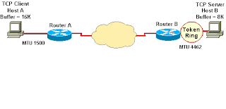
Fragmentation and TCP MSS , MPTUD : TCP Maximum segment size and TCP Path MTU Discovery play important role in fragmentation. Let us see first about TCP MSS TCP maximum segment size defines maximum amount of data receiver is willing to accept in single TCP/IP stream . How MSS is calculated for TCP/IP stream : MSS calculation is done based on buffer size in both server and client side During TCP/IP connection setup , The SYN segment contains MSS option. If machine does not want to mention MSS , a default of 536 bytes is assumed. The default value of 536 is derived from 576 minus 40 bytes of header which includes 20 bytes of each ip and tcp header. Please note that MTU of dial up connection is 576 Diagram : 1 . Host A sends MSS of 16 k 2 S 2 . Server receives SYN and sets send MSS of host A to 16k 3 S 3 . Server sends MSS of 8k 4 H4. Host A receives and sets send MSS of server to 8k. Here MSS is based on minimum buffe

IP Fragmentation Reassembly

IP Fragmentation : If the MTU of egress network is less than MTU of packet and DF bit is set to 0, then fragmentation is needed . Fields involved in fragmentation : 1 . Fragment id 2 . offset 3 . Flag Fields changed when fragmentation : Apart from above 3 , following fields are changing in fragmentation 1 . Header length and total length 2 . Header checksum 3 . Options A Packet Fragmentation Example If a 2,366 byte packet enters an Ethernet network with a default MTU size, it must be fragmented into two packets. The first packet will: · Be 1,500 bytes in length. 20 bytes will be the IP header, 24 bytes will be the TCP header, and 1,456 bytes will be data. · Have the DF bit equal to 0 to mean "May Fragment" and the MF bit equal to 1 to mean "More Fragments." · Have a Fragmentation Offset of 0. The second packet will: · Be 910 bytes in length. 20 bytes will be the IP header, 24 bytes will be the TCP header, and 866 bytes will be

Packet over SONET/SDH

Image
Packet Over SONET/SDH : Many of us use the POS interfaces in the routers . So here we will have one small technical summary about POS(packet over SONET/SDH) POS also known as PPP over SONET/SDH . This is scheme which uses PPP encapsulation to map IP datagrams into the SONET/SDH payload . Why SONET/SDH payload and PPP are used for enacapsulation : Since SONET/SDH is point to point circuit , PPP is well suited here . POS layers : There are three pos layers. They are 1 . Bottom layer : mapping into SONET/SDH 2 . Mid layer - Framing of PPP with HDLC . 3 . Top layer – IP encapsulation into PPP Here I rememember Sridhar G , my mentor in HCL . I created the stream for POS interface and traffic was not success . At that time , he told me to select the HDLC in Agilent RT. For Ethernet , We use some other encapsulation in RT. Please share that info if u know. Operation of POS is : When transmitting : IP -> PPP->FCS generation->Byte stuffing->scrambling-SONET/SDH framing When rec

How Ping and Trace route work

Trace Route Process A . Traceroute sends out 3 ICMP echo packets to the named host, but with a TTL of 1; then with a TTL of 2; then with a TTL of 3 and so on. Traceroute will then get 'TTL expired in transit' message back from routers until the desination host computer finally is reached and it responds with the standard ICMP 'echo reply' packet. Please note that TTL increment happens till destination is reachable or TTL reaches its maximum value. Trace route is mainly used in troubleshooting of the networks Possible ICMP error messages in trace route : H :- Host unreachable. The router has no route to the target system. N :- Network unreachable. P :- Protocol unreachable. S :- Source route failed. You tried to use source routing, but the router is configured to block source-routed packets. F :- Fragmentation needed. This indicates that the router is misconfigured. X :- Communication administrative

OSI Layers

Image
In the early 1980s, the International Standards Organization (ISO) recognized the need for a standard network model. This would help vendors to create interpretable network devices. The Open Systems Interconnection (OSI) reference model, released in 1984, addressed this need. The OSI model describes how information makes its way from application programs through a network medium to another application program in another computer. It divides this one big problem into seven smaller problems. Each of these seven problems is reasonably self-contained and therefore more easily solved without excessive reliance on external information. Each problem is addressed by one of the seven layers of the OSI model. Layers - Functions - Devices The application layer The application layer of the OSI model is the layer